Challenges of Curved Touch Sensor Design

Estimated reading time: 7 minutes
Table of contents
Curved touch sensor requirements
1. High dielectric constant
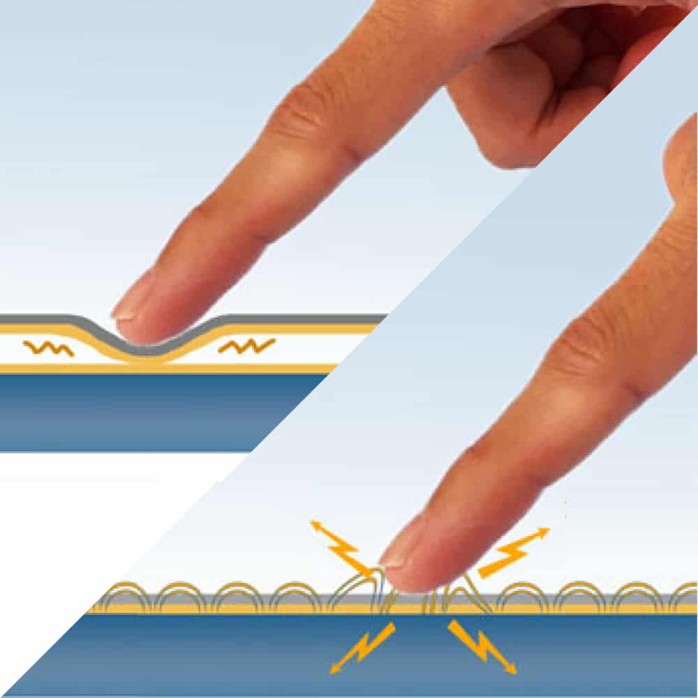
To ensure optimal touch sensitivity, a capacitive touch sensor must be as close as possible to the finger that activates the touch. Thus, both the overlay as well as the layers separating the sensing surface (ITO layer) from the finger must have a high dielectric constant (ε). The higher the dielectric constant of the overlay material(s), the thicker this overlay can be made.
Glass has a significantly higher dielectric constant (ε = 5-8) than plastics and adhesives (ε = 3-4), but both still much higher than that of air (ε = 1). A touch sensor can tolerate a relatively thick glass cover lens up to and exceeding 4mm, but plastic cover lenses above 2mm are already critical. However, any layer of air – even as thin as 0.2mm – will render a capacitive touch panel nearly useless.
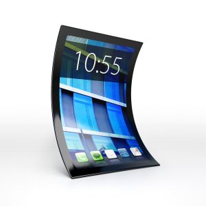
2. Flexibility or curved shape
This also means that touch sensors combined with curved cover lenses must follow the shape of the lens. Film-based touch sensors would be the ideal choice as they can easily be laminated onto a curved shape, as long as the curvature is cylindrical (in one direction) and not spherical (in two directions). Existing film lamination equipment would only have to undergo minor adjustments in order to enable lamination of film-based sensors to curved cover lenses.
However, film-based sensors have two main limitations compared to glass-based sensors:
- The storage temperature of film-based sensors is limited to about 85°C which, for example, is not sufficient for automotive applications.
- The optical properties of PET-film are not as good as those of glass. Compared to glass-based sensors, film sensors have a certain degree of haze, lower transparency and suffer from birefringence—a property that leads to a rainbow effect when viewed in polarized light (e.g. through polarized sunglasses).
Industry approaches to curved touch sensor design
There are several approaches and ongoing developments the industry is making in order to try and overcome the limitations of curved touch sensor design:
1. PET alternatives
The industry has developed different types of films with improved optical properties, specifically without birefringence (the effect of which becomes visible in polarized light):
- Cyclic Olefin Polymer (COP)
- Cellulose Triacetate (TAC)
Currently, these film types are used in polarizers, anti-reflective films that improve sunlight readability, and thus are likely to be viewed with polarized sunglasses.
Although used for decades, these films have not been considered suitable for touch sensors for two main reasons: (1) The relatively low cost of PET film, and (2) the difficulty in reliably coating such films with ITO in order to achieve the required adhesion or scratch resistance on those films. This difficulty has now been overcome with ITO-coated COP-films which are being commercialized. Furthermore, the ITO alternatives that have recently appeared on the market (e.g. metal mesh and silver-nano-wires) require completely different application processes which are much easier to apply on non-PET films. However, such sensors only overcome the birefringence limitation of PET film without improving the other optical properties and exposure to high temperatures.
2. In-mold sensors
Here, the film sensors are not laminated into an existing rigid plastic or glass lens. Instead, they are over-molded by the plastic in a similar way to how decorative elements are used in IMD-lenses. The limitation here is that the sensor films carrying the transparent conductive pattern have to be extremely robust and stretchable so that they survive the molding process without damage. ITO is a brittle material and even when extremely thinly coated does not tolerate such stretching without breaking.
Here, the sensor material technology of choice is CNT (Carbon Nano Tubes) which is another transparent conductive material that only recently achieved a transparency level at the required conductivity sufficient for touch sensors. The CNT material could be coated on either PET-film or other birefringence free films, depending on the optical requirements of the end product.
The limitation of this approach is that it can only be used in conjunction with curved plastic lenses and not with glass lenses.
3. Bending of thin, rigid glass
When glass is thinned down to a thickness 0.25mm or less it can be bent to a certain degree without breaking. This property is utilized when laminating glass sensors at this thickness onto curved glass lenses, however this process is in trial phases and has only been proven to work on a sample level. Due to the tension forced upon the glass during the lamination process, it is difficult to use liquid glue: The glass will always try to revert back to its natural flat shape and would have to be kept in its bent shape during the lamination process until the glue is cured.
Also, due to gravity, the liquid glue would not spread evenly on a bent surface. Therefore, OCA film would be the adhesive of choice for this process. It would be laminated on the flat glass first and then into or onto the curved lens. Even with flat glass, the yield of the dry OCA process is lower than that of liquid glue. For curved lenses, lamination yields are expected to be even lower due to the tendency of the bent glass to revert back to its flat shape. The greater the level of curvature, the lower that yield would be. Long term reliability of such a solution still has to be proven as the delaminating force will remain in the glass even after completion of the lamination process.
2. Use of film glass
Contrary to the above mentioned forcefully bent glass, film glass is truly bendable glass that behaves just like film and has the same level of thickness of approximately 0.1mm. This type of glass comes on a roll just like film and combines the advantages of film flexibility with the superior optical properties of glass. However, it is difficult to produce touch sensors with such thin glass specifically coating the ITO – or any other conductive transparent material – and etching the sensing pattern onto it. Regular plastic films are ITO coated and etched on a roll-to-roll process. In theory, glass film could be handled the same way due to its flexibility. However, it is still glass and can break. To reduce this risk, glass film edges would need to be reinforced as it runs through the roll-to-roll process because glass breaks typically originate from the edge. Trial lines have been set-up, but aren’t commercially available yet because the investments are huge and process control is extremely difficult.
Alternatively, film glass can be cut from the roll into large sheets and then laminated onto a rigid carrier. This allows the application of regular sheet glass ITO coating and etching process to the film glass. The film glass would then have to be removed from the carrier and then cut to individual sensors before eventually laminating the sensor to the curved lens. Such a process is costly and has a high potential for yield loss during the lamination and delamination processes.
The film glass solution is unlikely to be pursued unless all of the other solutions mentioned above prove to have significant flaws or disadvantages applicable to a wide range of curved touch sensor applications that can only be overcome with the use of glass film.