How Do LCDs Work?
Estimated reading time: 5 minutes
Table of contents
Polarization of Light
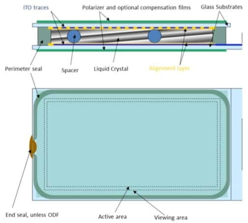
On the most basic level, most (not all) types of LCDs change the polarization state of light passing through a layer of liquid crystal material. The geometry of that layer is controlled by a competition between boundary conditions and an applied electric field. Usually, for this type of LCD, nematic liquid crystals are used with special coatings applied to the rear and front substrates. The coatings serve to create the boundary conditions and to apply the required electric field. On the outside of the LCD cell, optical films (including polarizer films) are attached. They translate the change in polarization of the light into a bright and dark contrast. The display structure gets assembled in such a way that zero applied field gives one extreme brightness state and fully applied field results in the other extreme. An intermediate field creates an intermediate brightness level.
Boundary Conditions
Material selection
The most common materials used to impose boundary conditions are called polyimides.
A solution (or a precursor) of a polyimide is deposited on the substrates and cured. The type of polyimide and the type of liquid crystal define what angle the liquid crystal molecules will assume at the contact point between the polyimide and the liquid crystal:
- If the materials are ‘similar’, the LC molecules lay flat.
- If they are dissimilar (like oil and water), the LC molecules stand upright.
Rubbing direction
‘Molecular engineering’ is used to achieve the ideal angle for the application, which is different for different kind of displays.
In order to define the direction of alignment, the polyimide surface is unidirectionally rubbed or brushed. LC molecules align parallel to that rubbing direction. If the angle and rubbing direction do not match on the two alignment surfaces, the liquid crystal alignment is elastically deformed.
The nematic LC molecules want to be parallel to each other, but if the rubbing direction on either surface is orthogonal, the LC molecules are forced to twist very slightly from molecule to molecule until across the entire layer the direction has turned by 90°.
Modes of LC Deformation
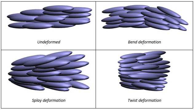
There are three principal modes of deformation possible in a nematic liquid crystal. Each has its own elastic constant (spring constant). Some deformation may require more or less force, depending on the molecular structure of the liquid crystal.
The three principal modes of deformation are called:
- splay,
- bend,
- and twist.
Applying an Electric or Magnetic field
The most common way to apply a force to deform the liquid crystal structure is applying an electric field (magnetic would also work) across the liquid crystal layer or parallel to the liquid crystal layer.
Conductive materials & application
In order to apply the field, it is necessary to have a transparent conductor so that the effect of the liquid crystal on light can be observed. Indium-Tin-Oxide (ITO) is such a conductor.
LCD manufacturers either buy ITO coated glass, or do the ITO coating as part of the manufacturing process. The ITO layer gets defined into shapes and patterns as needed by photolithography. The shapes and patterns of the two ITO layers (front and back) define the pixels and icons on the display.

Strength of electric field
In an applied field, the liquid crystal molecules want to align with respect to the field in such a way that the energy is minimized.
- If the field is strong enough, the molecular order imposed by the boundary conditions is overcome and the field determines the alignment of the molecules.
- If the field is weaker, the structure is deformed by the field.
In either case, when the field is removed, the effect of the boundary conditions takes over and the liquid crystal alignment returns to the state before field application. It behaves like a spring that gets deformed when a force is applied, then returns to its original shape when the force is removed.
Summary
In summary, the combined structure acts as an electrically tunable shutter that lets more or less light pass through.
